
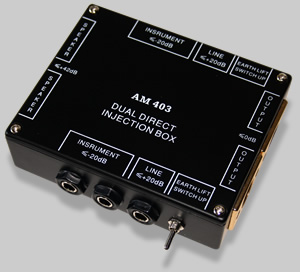
The new price of an AM 403 Dual Direct Inject Box can be around AUD $60 on eBay (includes postage). Realistically speaking, you probably couldn't buy the parts inside it for that money, let alone fabricate a case and pair of circuit boards.
I've never seen a used AM 403 for sale, but if one came along for under AUD$40, it would be worth buying, if only for the two balanced output transformers.
My suspicion though is that anyone who has one of these will be keeping it ;-))
GEAR RELATED ARTICLES
[Home Music Recording Studio]
GUITAR AMPLIFIERS:
Acoustic 450 - 170W Guitar / Bass Amp Head
Behringer Ultrabass BXL1800A 180W Bass Amp
Fender Princeton Chorus 51W Compact Amp
GUITARS:
Aspen AD25 6 String Acoustic Guitar
Esteve Model 8 Classical Guitar
La Patrie Concert CW QIT Classical Guitar
La Patrie Presentation Classical Guitar
Fender DG-14SCE Nat Acoustic Guitar
Godin XtSA Electric Guitar
Godin Freeway Classic Electric Guitar
Ibanez RG8 8 String Electric Guitar
Jim Beam Devil's Cut 335 clone
Maton EM125C - 6 String Acoustic Guitar
Maton EM425C/12 12 String Acoustic Guitar
Maton Mastersound MS500 - 6 Str Electric Guitar
Yamaha FG-410-12A 12 String Acoustic
Yamaha G-228 6 String Classical
GUITAR FX - The Chronicles of Zoom:
ZOOM GFX-707 - Review and Description
ZOOM 707 II - Review and Description
ZOOM BFX-708 - Bass Guitar Multi Effects Pedal
ZOOM G9.2tt - Guitar Effects Console
Behringer EM600 Echo Machine Stomp Box
Behringer RV600 Reverb Machine Stomp Box
ROLAND U-220 - Vintage Sound / Synth Module
SN-U110 and SN-MV30-S1 Series PCM Cards
Behringer FBQ1502HD Ultragraph Pro
Behringer Eurorack Pro RX1602 Rackmount Mixer
Capabilities of the CASIO WK-7500 Workstation
Presonus Eris E5 Powered Monitor Speakers
Vonyx (Skytec) SPJ-1000A Active 10" Speaker
[ Advertising ]
An amplifier Dummy Load is used to replace a loud speaker (or box thereof), when for example, testing an amplifier or in this case, sending the amp's output to a DI Box.
Why would anyone want to do this? you ask.
Answer: It's a great way to capture the full output of an amplifier and shunt that directly into some recording gear via a DI Box. Thereby capturing the full nuance of both pre and power amplifiers.
Essentially a Dummy Load is little more than an adequately rated resistance across the amplifier's output (speaker terminals).
While this article is mainly about a Dummy Load to work with a Direct Injection Box (see at right), the main and original purpose for Dummy Loads was for use in testing power amplifiers, so a quick diversion into that arena follows.
A Dummy Load is primarily used for testing the output capability and also stability of audio power amplifiers. For example, to measure the maximum RMS output at a given frequency into a specific load, like: Watts RMS @ 1KHz into 8Ω.
For testing purposes, It is generally a good idea for the Dummy Load to be able to handle at least twice (+6dB) the expected maximum RMS output of the amplifier. Three times the max RMS out is probably a better (safer) option to allow for high power transients.
Depending on the length of a test run, some kind of cooling may also be required or the resistors may eventually fail from prolonged overheating. I can recall one DIY design from years ago that was water cooled. The thinking was that this approach would dissipate heat more quickly than air cooling.
I suppose you could always make a cuppa while you were at it.
There are plenty of options/designs on the net for Dummy Load units including ones with switched loads (4, 8, 16 ohm) and there are all manner of 'how to articles' on YouTube.
Just bear in mind that a Dummy Load failure at high outputs could lead to substantial and expensive amplifier damage ... so be very careful.
I mention this because I'm not interested in getting emails telling me that someone made their own Dummy Load after reading this article and then ended up Irreparably destroying their $2,000 power amp.
So, a couple of simple points.
- If you don't know what you're doing and have no electronics experience, find someone who does (or preferably someone who can teach you).
- and/or buy a purpose built and ready made product that comes with an instruction manual and hopefully a warranty. I will bet however that they won't provide a warranty that covers your amp ;-)
After all of that, making your own amplifier Dummy Load can be stupidly simple if you have access to a workshop, some tools and the right parts.
While the circuit for an amplifier Dummy Load is about as simple as it gets, selecting the parts should be done with care. The consequences of getting it wrong could be costly. You have been warned (now several times :-)
Click the image below for a larger version...
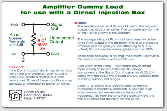
The information in the Pic above is reproduced here with additions.
NOTES:
Resistance:
The resistance value of RL (Resistive Load) should match the required output load of your amplifier. This will generally be 4, 8 or 16Ω (Ω = ohm). Some amps (particularly valve amps) have selectable output resistance. 8Ω resistance is shown in the diagram. This resistance may be made up using more than one physical resistor.
Resistance accuracy is not that important in this case. However a 5% resistor is preferable to a 10% one. For test equipment closer tolerances (1% or 2%) are preferred.
Power Handling / Wattage:
The wattage rating of RL should be at least twice the rated RMS output of the amplifier. This is to protect the amplifier (not the gear you are attaching to it). It is unlikely that the useful value of RL will ever be meaningfully less than 50W.
Handling Heat:
If the Dummy Load is connected to a high power amp running at high output your resistor(s) may get hot over time and therefore need to be mounted on a heatsink. I put them on a heatsink regardless. It's easier to do it all from the outset rather than have to modify things later (see photo below).
DC Voltages at the Output:
Also worth mentioning ... with some power amps there is likely to be a substantial DC voltage component at the Signal Out. A capacitor (0.22µf) in series with the output will prevent any DC voltages from reaching subsequent stages (not shown in the diagram).
Resistive and Inductive Loads:
A resistor is a resistive load and the resistance is constant regardless of frequency. A speaker is an inductive load, where resistance varies with frequency. So from the amplifier's point of view, the two are similar but definitely not the same. There is plenty of techy info out there on inductive loads if you want the specifics. In short, a Dummy Load is a workable replacement for a speaker, if you accept the limitations.
Connections / Cables
Just be aware that the Dummy Load is being used in place of a speaker (or box thereof). 6mm (1/4") mono phono sockets and jacks will work just fine as connectors. Then you will want a speaker cable to connect the amplifier to the Dummy Load and another speaker cable to connect the Dummy Load to the DI Box. Due to the working voltages at amplifier outputs (e.g.: around 25Volts @ 100Watts), you are likely to ruin any guitar leads used in place of proper speaker leads. Guitar leads are generally designed to handle only around 1/2V (a.k.a. 500mV).
Important: (yeah, I know...) If the Dummy Load fails, it may either blow like a fuse, creating an open circuit or (less likely) create a short circuit (zero resistance). Either of these conditions may damage an unprotected power amplifier.
Hint: Build it - to not break!
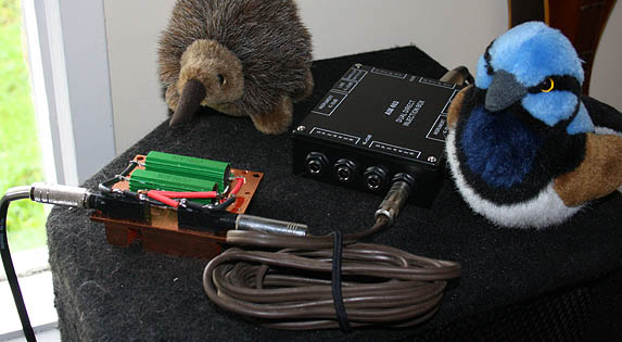
Dummy Load shown above plugged into AM 403 Dual DI Box (with friends).
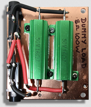
A top view of a single channel home-made Dummy Load (which is close to actual size).
The two 50W 16Ω (16 ohm) resistors (readily sourced from eBay) are wired in parallel to give a combined power handling capacity of 100W into 8Ω.
FYI: There are ready to go single 100W 8Ω resistors available, the 16Ω resistors were just what I had on hand at the time I decided to build this unit.
The resistors are mounted onto a copper processor heatsink salvaged from a micro PC. Heat-sink compound has been applied for maximum thermal transmission. Note that the bottom of the resistors had to be filed flat first to remove manufacturing burrs that would have prevented proper thermal contact between the two surfaces.
The wiring used is solid copper (32A) mostly just to make the finished item both robust and rigid. I'd rather have too much physical support than too little.
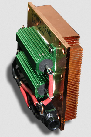 The casing (green) around the resistors is aluminium, and a heatsink of the same would have done just fine. Mounting the resistors into a metal box/case may also work if there is adequate surface area and good thermal contact to quickly dissipate any heat generated.
The copper heatsink shown (which has considerable thermal mass) has only ever become slightly warm to the touch using my 20W Ceriatone valve amp. And that was after hours of running (and on a warm day ;-)
For most practical purposes it's unlikely that this particular heatsink will ever become dangerously hot, but it is something to consider when using higher powered amps and more compact, lower density heatsinks.
Have fun, and take care.
Was this page useful?
Rate This Page:
| Page Ratings so far ... | ||
| Excellent | 10 | |
| Very Good | 0 | |
| Useful | 0 | |
| Not Useful | 0 | |
| TOTAL | 10 | |
Page online for years
Your Comments:
220725 - (Excellent) Very useful but I need more info. (But it's just me!)
Editor's Note: Ok?. Not sure what I could add, other than perhaps a suggestion to watch a few YT videos.
![]()
Incept Date: Wizard - 160510
Last Update: Wizard - 230901
